Hierarchical IP Core Generator for Quantum Fourier Transform Implementation in FPGA
| |
Quantum computers consist of two parts - a classical computer and its quantum coprocessor or
accelerator. The functioning of the main elements of a quantum coprocessor is described by a wave
function. You can create digital elements in FPGAs, the operation of which will be described by the
wave function, so called digital qubits. Due to the high computational complexity of quantum
computing such as Shor’s algorithm of factorization, VHDL-descriptions of digital quantum units must
be created for their implementation in FPGA. We offer a hierarchical generator of FPGA cores for
quantum Fourier transform implementation which is part of Shor’s algorithm. The generator creates
descriptions of both homogeneous and heterogeneous coprocessors. In addition, the generator creates
test circuits to check the generated coprocessors. This makes it possible to study the created
coprocessors, compare results of their functioning with ones of real quantum coprocessors and
analyze them.
Shor’s algorithm
In Shor's
algorithm, the problem of factorizing the
number M is
reduced to the problem of determining the
period r of the
function y = axmodM,
which is
calculated by the controlled units CU (Fig. 1),
where a is an
arbitrary integer. This is precisely the problem that a quantum computer solves. It is shown
that the greatest common divisor GCD(ar/2+1,
M) can be a
divisor of the number M. The
subsequent finding of the greatest common divisor is performed by a classical computer.
If  is the
required number of bits to represent the
number N to be
factored than the upper quantum register in Fig. 1 requires at
least 2n qubits,
because Shor’s algorithm requires x to take
values between 0 and at least N2 and the
modular exponentiation function can be written as
is the
required number of bits to represent the
number N to be
factored than the upper quantum register in Fig. 1 requires at
least 2n qubits,
because Shor’s algorithm requires x to take
values between 0 and at least N2 and the
modular exponentiation function can be written as  .Shor's
algorithm
takes O(b3) time
and O(b) space
on b-bit
number M inputs.
.Shor's
algorithm
takes O(b3) time
and O(b) space
on b-bit
number M inputs.
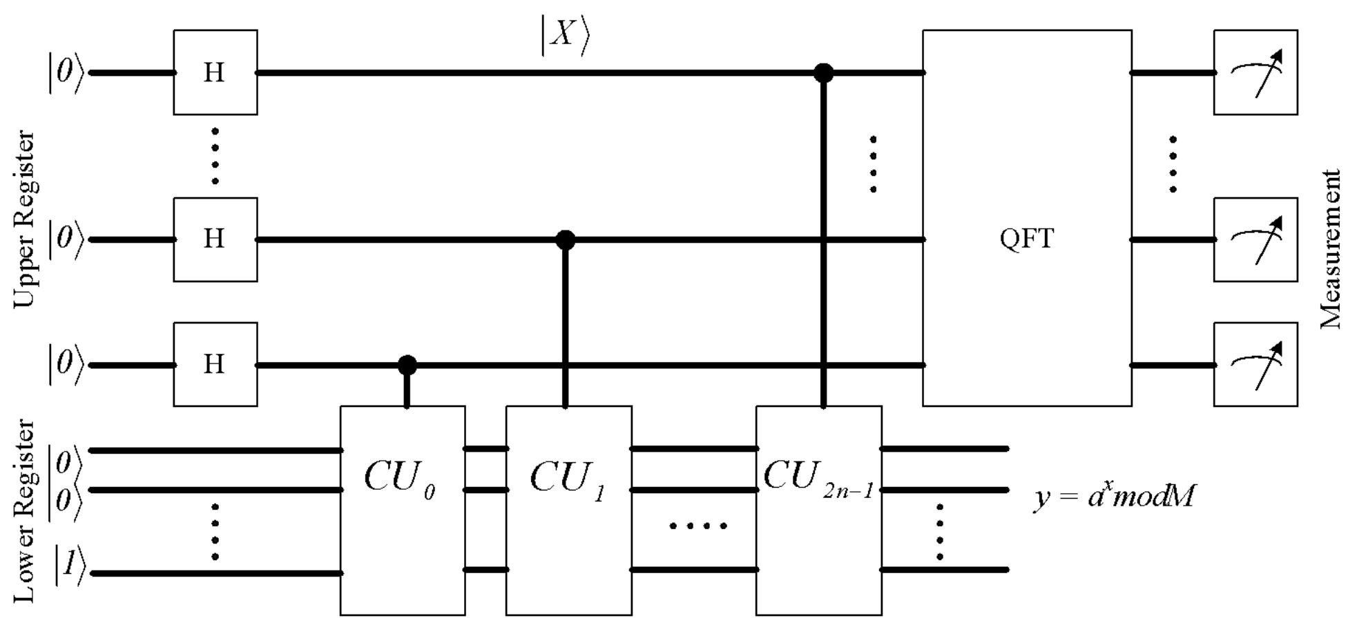
Fig. 1. Shor’s algorithm implementation
Each unit
CUj calculates
the value  , and unit
CUj-1 finds
the inverse function with respect to CUj.
, and unit
CUj-1 finds
the inverse function with respect to CUj.
QFT is used in
calculations by the Shor algorithm. Its complexity is estimated
as O(q),
where q is the
number of qubits. In addition, the QFT scheme (Fig. 2) uses only simple quantum gates, and there
is no need to calculate inverse functions. This makes it easy to implement the QFT digitally
using FPGA (Fig. 3).
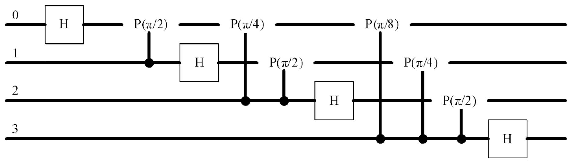
Fig. 2. Classical drawing of QFT (4-qubits)
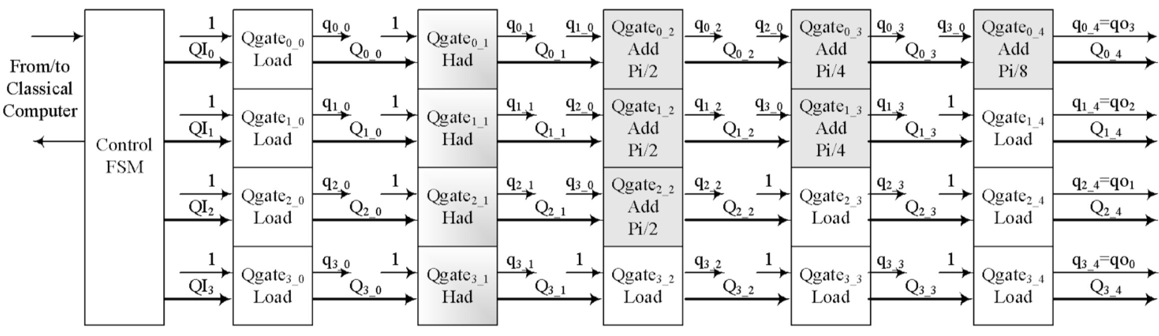
Fig. 3. Simplified drawing of QFT generated FPGA schema (4-qubits)
More
difficulties arise when testing implemented on an FPGA circuit Fig. 3. So far, it has been
possible to show its correct operation with a limited number of input vectors.
IP Core
Generator hierarchy
The high
computational complexity of quantum algorithms makes it necessary to create special core
generators for FPGAs.
First of all,
a core generator for a quantum Fourier transform was created. The proposed core generator has a
hierarchical structure.
The lowest
level of the hierarchy is the level where digital quantum logic gates Fig. 4 are synthesized.
The quantum logic gate includes an ALU, a comparator, and a pipelined register. ALU performs one
of the conditional quantum operations. In this case, the code DataIn of the digital qubit
previous state changes and turns into an output code DataO. The comparator compares this code
with a random value Asin_f and forms the measured state of the qubit after performing the
specified operation. The code of the new state of the qubit DataOut and its measured
value  (after
performing this operation) is issued from the output of the pipeline register RG.
(after
performing this operation) is issued from the output of the pipeline register RG.
In
heterogeneous quantum coprocessors, each quantum gate receives its own random code for
comparison. A schematic diagram of a digital quantum cell for this case is shown in Fig. 5. Near
to the digital quantum gate is a pseudo-random number generator PRNG and a functional
transformer  . The level of
digital quantum cells is the second level of the hierarchical core generator.
. The level of
digital quantum cells is the second level of the hierarchical core generator.
In this case,
a digital qubit is formed by a serial connection of digital quantum cells (Fig. 6).
In homogeneous
quantum coprocessors, all quantum gates receive the same random code for comparison. A schematic
diagram of a digital quantum qubit for this case is shown in Fig. 7.
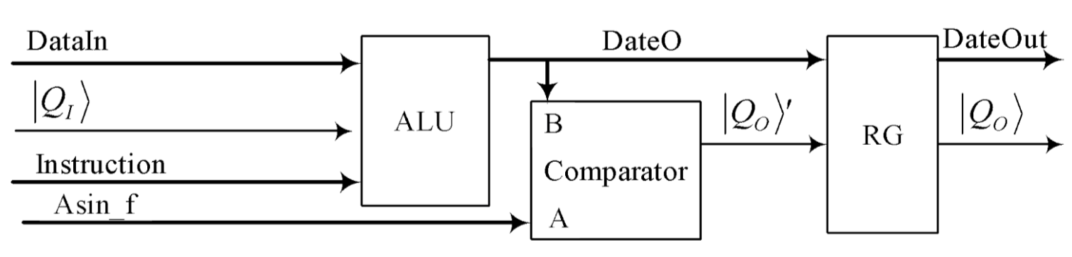
Fig. 4. A digital quantum gate Qgate
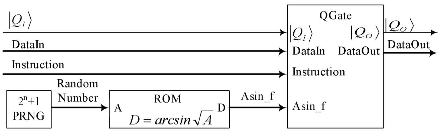
Fig. 5. A digital quantum cell DQCell for heterogonous digital quantum coprocessor.
The
generalized scheme of a homogeneous digital quantum coprocessor is shown in the Fig. 9. There is
only one pseudo-random number generator PRNG and one functional transformer in
coprocessor.
The digital
qubit level is the third level of the hierarchical core generator.
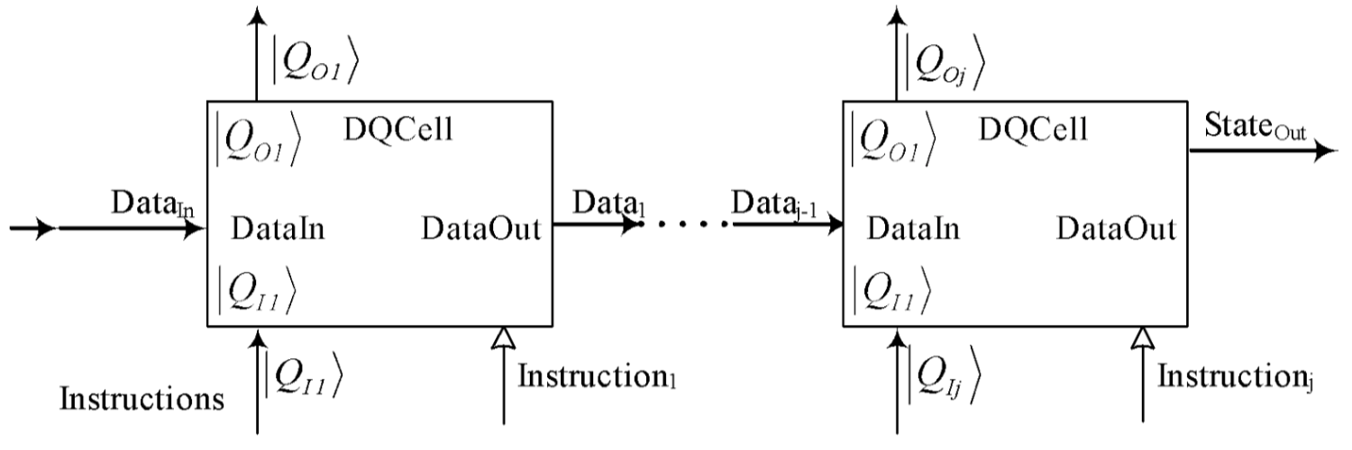
Fig. 6. A digital quantum qubit as line of DQCells for heterogonous digital quantum coprocessor.
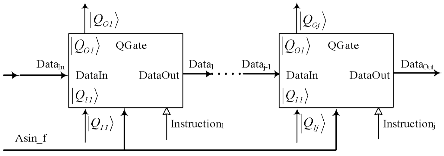
Fig. 7. A digital quantum qubit as line of DQGates for homogenous digital quantum coprocessor.
The classical
scheme of the quantum Fourier transform is shown in Fig. 2. The same circuit based on the
generated elements is shown in Fig. 3.
A testbench
for simulating the operation (forth level) of the generated coprocessors is shown in Fig.
8.
The testbench
includes a Control Unit, an input register QiRgN, a coprocessor QFTN and a Test Unit for
analyzing the results of the coprocessor operation (N is the number of qubits in the
coprocessor, up to 1024). The test unit determines how often correct results appear on the
coprocessor output. This is the fourth level of the hierarchy.
The fifth
level of the hierarchy is the program of the control unit (in Fig. 8, N is digital qubits
number) and global variables generation. And the highest level is the simulator.
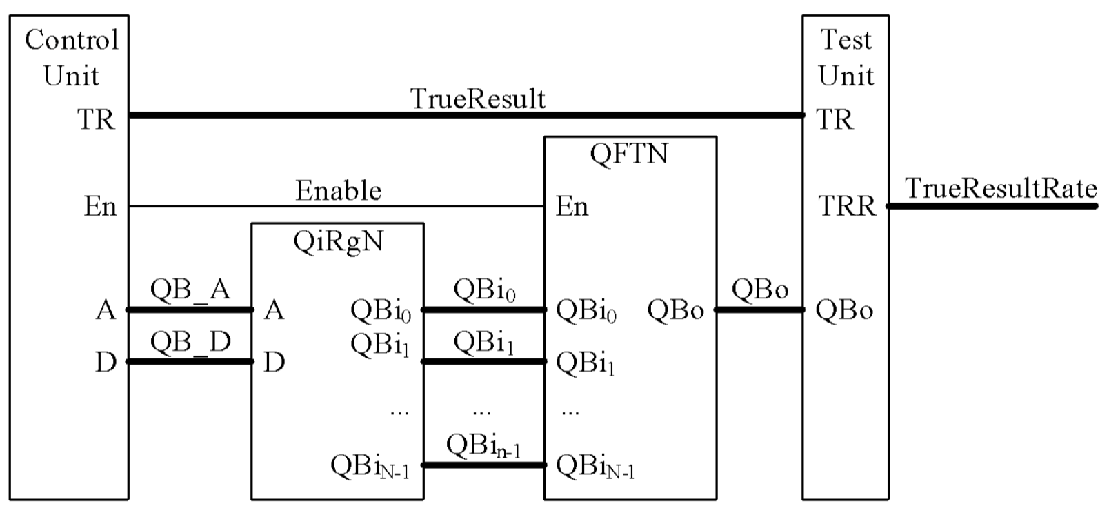
Fig. 8. Digital Quantum Coprocessor Testbench
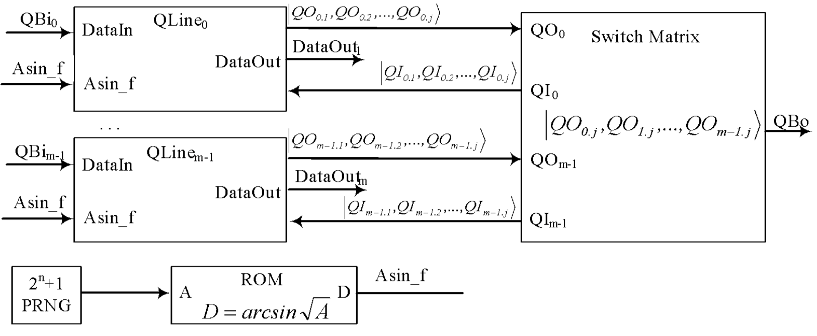
Fig. 9. A generalized functional diagram of a digital quantum coprocessor.